Vadodara
+919979119649

'one linear inch'

Items tagged with 'one linear inch'

product image
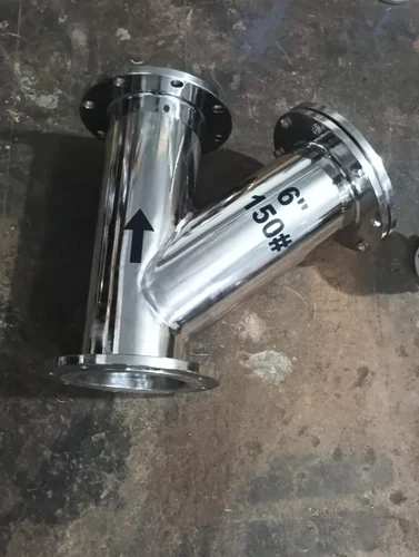
Strainer

NRG GLOBAL MAKE Basket strainers are installed to protect equipment from damage caused by unwanted debris that may be in the pipeline. The unwanted debris could be dirt or other foreign particles that make their way into the process fluid. Typically, basket strainers are installed in horizontal pipelines and in situations where high flow capacity is required. These strainers are installed upstream of equipment like pumps, control valves, and traps, keeping potentially corrosive or damaging debris from making its way down the line. They can be installed alone or in a series to increase filtration. They may come with a single chamber (simplex strainers) or multiple chambers (multiplex strainers). To read more about the differences between simplex and duplex strainers, check out this post. Understanding Mesh Sizing Each strainer is designed with a mesh lined basket to filter and collect the unwanted debris. Mesh size should be chosen based on the job function, not the size of the system. Selecting a mesh with openings that are too small could result in more frequent clogged lines, while a mesh with significantly larger openings could permit more unwanted debris to flow through the pipeline and equipment. Ideally, then, you’ll want to choose a mesh where the perforation is slightly smaller than the smallest particle you’ll need to filter out. Mesh size is measured by the number of openings in one linear inch of screen. For instance, a 16-mesh screen would have 16 openings per inch, while a 100-mesh screen would have 100 openings. Higher numbers, therefore, are able to strain out smaller particles with a finer weave. The baskets are typically made of stainless steel for quality and durability. Factors for Selecting the Right Basket Strainer Each application could require a different basket strainer. Consider the unique functions of your pipeline before deciding on a strainer. Important factors include the pressure and temperature requirements of your line, the type of liquid flow (corrosive, abrasive, etc.), debris size, and the frequency of cleaning and maintenance. You may also consider a duplex style basket strainer (such as these), which holds two strainer baskets fed by diverting valves. This system allows one basket to be cleaned and serviced while the other maintains flow.

Send Message
product image
Flow Instruments

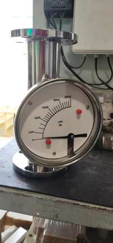
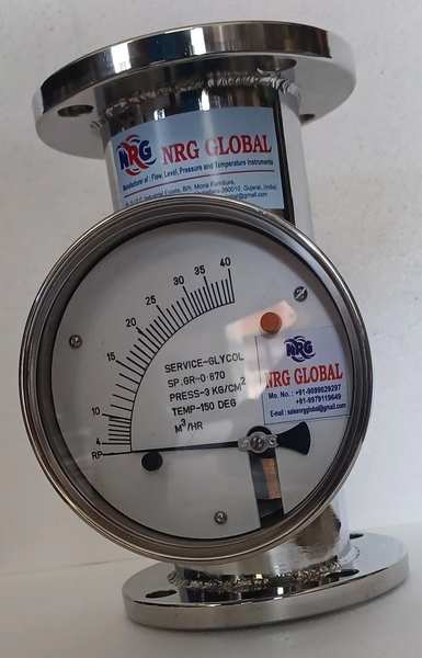
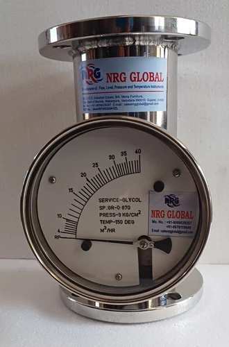
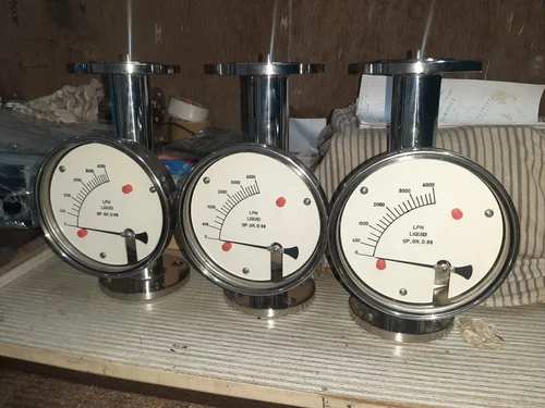
NRG GLOBAL MAKE Metal Variable Area Type Flow Meter are designed to measure flow rate of liquids and gases under critical conditions. It consists of a tapered metal tube, an indicating assembly and float. A magnet encapsulated in float couples with rotating magnets are connected to an indicating pointer. Henceforth, the movement of the float is accurately indicated in terms of flowrate. They are intended for application where high pressure, temperature or corrosive conditions preclude the use of conventional glass tube. These are all Metal Variable Area Type Flow meter design to measure flow rate of Liquids & Gases under critical conditions. It consists of a tapered metal tube, an indicating assembly and a float. A magnet encapsulates in float couples with rotating magnets connected to an indicating pointer, thus the movement of the float, is accurately indicated in terms of flow rate. 2. Working Principle When fluid or gas flows through a taper tube containing a float, a pressure difference of P1 and P2 is created between upper and lower side of the float. The float moves upwards by a force obtained by multiplying the pressure differential by the maximum cross-sectional area of the float. Based on Bemoulli's theorem, the principle mentioned above can be theoretically expressed as follows. Due to taper tube, as the float moves upwards, the fluid passing area increases as a result of which the differential pressure decreases. Upward movement of float stops when the dead load is dynamically balanced by the differential pressure. Tapering of metering tube is so designed that the vertical movement of the float becomes linearly proportional to the rate of flow and the scale is provided to read the position of the float, thusgiving birth to flow rate indication.

Send Message
product image
Flow Rotameter

Metal Variable Area Type Flow Meter are designed to measure flow rate of liquids and gases under critical conditions. It consists of a tapered metal tube, an indicating assembly and float. A magnet encapsulated in float couples with rotating magnets are connected to an indicating pointer. Henceforth, the movement of the float is accurately indicated in terms of flowrate. They are intended for application where high pressure, temperature or corrosive conditions preclude the use of conventional glass tube. These are all Metal Variable Area Type Flow meter design to measure flow rate of Liquids & Gases under critical conditions. It consists of a tapered metal tube, an indicating assembly and a float. A magnet encapsulates in float couples with rotating magnets connected to an indicating pointer, thus the movement of the float, is accurately indicated in terms of flow rate. 2. Working Principle When fluid or gas flows through a taper tube containing a float, a pressure difference of P1 and P2 is created between upper and lower side of the float. The float moves upwards by a force obtained by multiplying the pressure differential by the maximum cross-sectional area of the float. Based on Bemoulli's theorem, the principle mentioned above can be theoretically expressed as follows. Due to taper tube, as the float moves upwards, the fluid passing area increases as a result of which the differential pressure decreases. Upward movement of float stops when the dead load is dynamically balanced by the differential pressure. Tapering of metering tube is so designed that the vertical movement of the float becomes linearly proportional to the rate of flow and the scale is provided to read the position of the float, thus giving birth to flow rate indication. 3. Specifications Accuracy : ± 2% of FSD Rangeability : 10:1 Repeatability : ± 0.5% Temperature Rating : -200 to 250°C Pressure Rating : 40 Bar Flow Direction : Bottom to Top Connections : Flanged, TC End and Screwed Enclosure : IP 65 Weatherproof 4. Design features 1. Simplified piping and reduced space requirements 2. Permanent magnetic link between metering float and motion position transmitter 3. Precision swaged metering tube 4. Guide cartridges easily removable for cleaning 5. Provide with Electrical transmitter, flow indicator or alarm 6. Available F/F Height in 350, 450, 500 mm 7. Available Flange size 15 NB to 150 NB & Flow 200 LPH to 50,000 LPH

Send Message
product image
Metal Tube Rotameter

Metal Variable Area Type Flow Meter are designed to measure flow rate of liquids and gases undercritical conditions. It consists of a tapered metal tube, an indicating assembly and float. A magnetencapsulated in float couples with rotating magnets are connected to an indicating pointer. Henceforth,the movement of the float is accurately indicated in terms of flowrate.They are intended for application where high pressure, temperature or corrosive conditions precludethe use of conventional glass tube. These are all Metal Variable Area Type Flow meter design to measureflow rate of Liquids & Gases under critical conditions. It consists of a tapered metal tube, an indicatingassembly and a float. A magnet encapsulates in float couples with rotating magnets connected to anindicating pointer, thus the movement of the float, is accurately indicated in terms of flow rate.2. Working PrincipleWhen fluid or gas flows through a taper tube containing a float, a pressure difference of P1 and P2 iscreated between upper and lower side of the float. The float moves upwards by a force obtained bymultiplying the pressure differential by the maximum cross-sectional area of the float.Based on Bemoulli's theorem, the principle mentioned above can be theoretically expressed asfollows. Due to taper tube, as the float moves upwards, the fluid passing area increases as a result of which thedifferential pressure decreases. Upward movement of float stops when the dead load is dynamically balanced by the differential pressure. Tapering of metering tube is so designed that the vertical movement of the float becomes linearly proportional to the rate of flow and the scale is provided to read the position of the float, thusgiving birth to flow rate indication.

Send Message
product image
Industrial Rotameter

Metal Variable Area Type Flow Meter are designed to measure flow rate of liquids and gases under critical conditions. It consists of a tapered metal tube, an indicating assembly and float. A magnet encapsulated in float couples with rotating magnets are connected to an indicating pointer. Henceforth, the movement of the float is accurately indicated in terms of flowrate. They are intended for application where high pressure, temperature or corrosive conditions preclude the use of conventional glass tube. These are all Metal Variable Area Type Flow meter design to measure flow rate of Liquids & Gases under critical conditions. It consists of a tapered metal tube, an indicating assembly and a float. A magnet encapsulates in float couples with rotating magnets connected to an indicating pointer, thus the movement of the float, is accurately indicated in terms of flow rate. 2. Working Principle When fluid or gas flows through a taper tube containing a float, a pressure difference of P1 and P2 is created between upper and lower side of the float. The float moves upwards by a force obtained by multiplying the pressure differential by the maximum cross-sectional area of the float. Based on Bemoulli's theorem, the principle mentioned above can be theoretically expressed as follows. Due to taper tube, as the float moves upwards, the fluid passing area increases as a result of which the differential pressure decreases. Upward movement of float stops when the dead load is dynamically balanced by the differential pressure. Tapering of metering tube is so designed that the vertical movement of the float becomes linearly proportional to the rate of flow and the scale is provided to read the position of the float, thus giving birth to flow rate indication. 3. Specifications Accuracy : ± 2% of FSD Rangeability : 10:1 Repeatability : ± 0.5% Temperature Rating : -200 to 250°C Pressure Rating : 40 Bar Flow Direction : Bottom to Top Connections : Flanged, TC End and Screwed Enclosure : IP 65 Weatherproof 4. Design features 1. Simplified piping and reduced space requirements 2. Permanent magnetic link between metering float and motion position transmitter 3. Precision swaged metering tube 4. Guide cartridges easily removable for cleaning 5. Provide with Electrical transmitter, flow indicator or alarm 6. Available F/F Height in 350, 450, 500 mm 7. Available Flange size 15 NB to 150 NB & Flow 200 LPH to 50,000 LPH

Send Message
product image
Magnetic Level Indicator

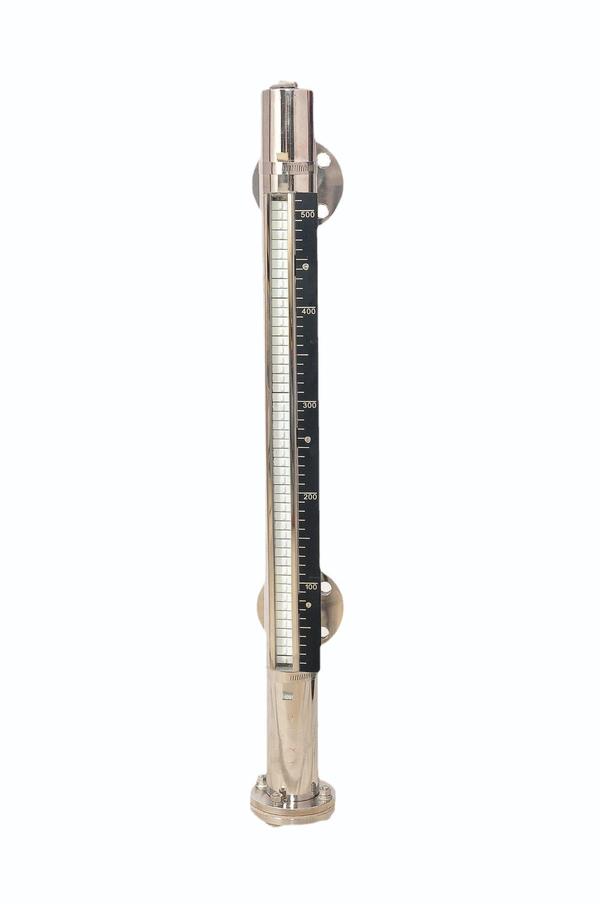
“NRG GLOBAL” make Magnetic Level Gauge provides clear, high clarity indication of liquid level. Magnetic Level Gauges are principally designed as an alternative to glass level gauges. NRG GLOBAL offers Magnetic Level Gauges in top-bottom, top and side mounted construction with two types of indicator system i.e. Capsule and Bi-colour Rollers. Magnetic Level Gauge is consists of three major components: Float Chamber, Float and Indicator System. Magnetic Level Gauge operates on the principle of magnetic field coupling to provide Fluid Level Information. Float chamber is typically constructed with nonmagnetic pipe having process Connections that matches to the vessel connections. Float size and weight is determined by the process fluid, pressure, temperature and the specific gravity of the process fluid. Float contains magnets to provide 360 ̊magnetic flux field.

Send Message
product image
Level Switch

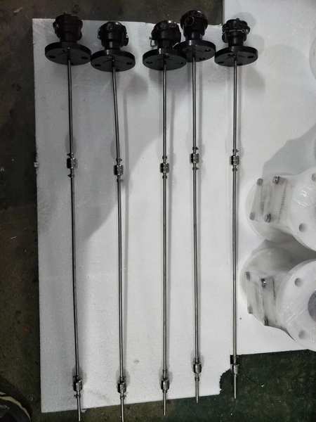
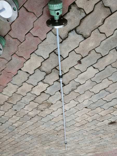
NRG GLOBAL INSTRUMENTS MAKE magnetically float operated Top Mounted Level Switch for controlling one or multi Levels by using reed Switch. The Unit Consists of Vertical Guide Pipe (Stem), Reed Switches Are located, Magnetic Float Sliding over the Stem according to the level in the tank. After passing the float, the reed relay will retain their output state. Various materials of construction are available depending up on Service Condition. Maximum 4 Set points can be given in a Single Level Switch & Maximum stem length will be 3 Meters. 2. Technical Data Float : S.S.316 / SS with PTFE / Poly Propylene Process Connection : Flanged / Screwed / TC Joint Flange : Mini 1” NB to Any Size in C.S. / S.S.304 / S.S.316 / SS with PTFE Coated / P.P. Switch : Hermetically Sealed Magnetically Operated Reed Switch with Rhodium Contact SPST / SPDT. Rating : 0.5 Amps @ 24 V DC OR 230 VAC 1 AMP Switch Housing : Die Cast Aluminum, Weather Proof IP 65 (Enclosure) / Flame Proof to II A, II B (IS – 2148 CMRS Dhanbad Approved) Operating Pressure : 10 Kg / Cm2 Operating Temp : Max. 90 C. Cable Entry : ½” NPT (F) OR ¾” ET (F) No of Switches : As Per Customer Requirement Stem Length : Up to 3 Meters.. other on your request Additional Information: Production Capacity: 100 Delivery Time: WEEK Packaging Details: EXPORT WORTHY PACKING

Send Message
product image
Level Switch

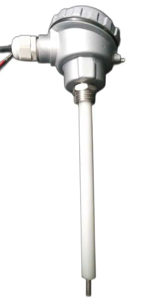
Conductivity Level Switch is a simple, low cost, point level measurement switch designed for level detection of conductive liquids having low densities, high viscosities, containing solid particles and to detect interface between non-conductive and conductive liquids. The probes work through the variation of the electrical resistance between the reference electrode and the level-control electrode. Conductivity level switches detect the level resistance when their electrodes are covered by the medium. If the tank is made of plastic, concrete, or any other nonconductive material, an additional electrode is required as a reference Conductivity Level Switches are available with stainless steel 316 electrodes as standard Suitable for many chemicals and aggressive media which are conductive in nature and dirty liquids, liquids with high solid content Construction available with both Solid probes & Suspended probes to suit fitting requirement It is a simple, low cost, point level controller designed for detecton of conductive liquids, having low densites, high viscosities, containing solid particles and interface between nonconductive and conductive liquids. CONSTRUCTION & OPERATION It comprises of a probe, wired to a level controller. The probe holds one common reference/common electrode and one or multiple “Control Electrodes” depending upon the number of levels to be controlled. All the electrodes are suitably insulated to avoid electrical bridging. The lengths of “Control Electrodes” correspond to the height of preset level points to be controlled and the length of the “reference/common Electrode” is kept slightly longer than the longest “Control Electrode”. If tank is conductive, it can be used as a reference/common electrode. Then number of control electrodes equals number of preset levels. Level controller houses sensing electronics consisting of power supply and signal conditoning circuit which provide a “Low AC Voltage” across mass and control electrodes. On liquid reaching preset level point electrical circuit gets completed - generating a signal which is amplified to actuate a relay, those potential free contacts are available for subsequent operations. On “Level Falling” the circuit breaks, deactivating the relay Additional Information: Production Capacity: 100 Delivery Time: WEEK Packaging Details: EXPORT WORTHY PAKING

Send Message
product image
Level Switch

1. Product Description NRG GLOBAL Introduced magnetically float operated Top Mounted Level Switch for controlling one or multi Levels by using reed Switch. The Unit Consists of Vertical Guide Pipe (Stem), Reed Switches Are located, Magnetic Float Sliding over the Stem according to the level in the tank. After passing the float, the reed relay will retain their output state. Various materials of construction are available depending up on Service Condition. Maximum 4 Set points can be given in a Single Level Switch & Maximum stem length will be 3 Meters. 2. Technical Data Float : S.S.316 / SS with PTFE / Poly Propylene Process Connection : Flanged / Screwed / TC Joint Flange : Mini 1” NB to Any Size in C.S. / S.S.304 / S.S.316 / SS with PTFE Coated / P.P. Switch : Hermetically Sealed Magnetically Operated Reed Switch with Rhodium Contact SPST / SPDT. Rating : 0.5 Amps @ 24 V DC Switch Housing : Die Cast Aluminum, Weather Proof IP 65 (Enclosure) / Flame Proof to II A, II B (IS – 2148 CMRS Dhanbad Approved) Operating Pressure : 10 Kg / Cm2 Operating Temp : Max. 90 C. Cable Entry : ½” NPT (F) OR ¾” ET (F) No of Switches : As Per Customer Requirement Stem Length : Up to 3 Meters 3. Design features 1. One Moving Component Exists, so that no – wear of float. 2. Suitable for any fluid having Specific Gravity Above 0.7 3. Minimum possible Distance between 2 Level set Points is 75 mm. 4. Accuracy : ± 0.10%, ± 0.25 %, ± 0.5 % on F.S. 5. The switch operates on the principle of magnetic flux coupling with no mechanical connection so that fluid contamination of switch components cannot occur. 4. Ordering Information Information Required to Quote: Material of Construction, Service Medium, Specific Gravity, Max. Pressure & Temperature, Number of Actuating Levels & Their Distance from top of the Connection, Process Connection.

Send Message

Still searching for
one linear inch?