Vadodara
+919979119649

'vendor catalog manual'

Items tagged with 'vendor catalog manual'

product image
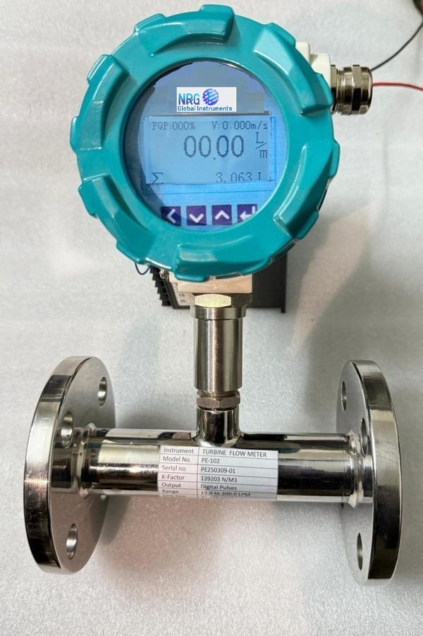
Flow Meter

NRG GLOBAL INSTRUMENTS MAKE Electromagnetic Flow Meters, simply known as mag flow meter is a volumetric flow meter which is ideally used for waste water applications and other applications that experience low pressure drop and with appropriate liquid conductivity required.The device doesn’t have any moving parts and cannot work with hydrocarbons and distilled water. Mag flow meters are also easy to maintain.Electromagnetic Flow Meters Principle of Magnetic Flow Meter Based on Faraday’s LawMagnetic flow meters works based on Faraday’s Law of Electromagnetic Induction. According to this principle, when a conductive medium passes through a magnetic field B, a voltage E is generated which is proportional to the velocity v of the medium, the density of the magnetic field and the length of the conductor. [E is the voltage generated in a conductor, V is the velocity of the conductor, B is the magnetic field strength and L is the length of the conductor].It is very important that the liquid flow that is to be measured using the magnetic flow meter must be electrically conductive. The Faraday’s Law indicates that the signal voltage (E) is dependent on the average liquid velocity (V), the length of the conductor (D) and the magnetic field strength (B). The magnetic field will thus be established in the cross-section of the tubeBasically when the conductive liquid flows through the magnetic field, voltage is induced. To measure this generated voltage (which is proportional to the velocity of the flowing liquid), two stainless steel electrodes are used which are mounted opposite each other.The two electrodes which are placed inside the flow meter are then connected to an advanced electronic circuit that has the ability to process the signal. The processed signal is fed into the microprocessor that calculates the volumetric flow of the liquid.Electromagnetic Flow Meters Formula:Electromagnetic flow meters use Faraday’s law of electromagnetic induction for making a flow measurement. Faraday’s law states that, whenever a conductor of length ‘l’ moves with a velocity ‘v’ perpendicular to a magnetic field ‘B’, an emf ‘e’ is induced in a mutually perpendicular direction which is given byThus the volume flow rate is proportional to the induced emf. In Practical applications we have to enter the meter constant ‘K’ value in magnetic flow meter which is available in vendor catalog/manual.Applications of Magnetic Flow MetersThis electromagnetic flow meter being non intrusive type, can be used in general for any fluid which is having a reasonable electrical conductivity above 10 microsiemens/cm.Fluids like sand water slurry, coal powder, slurry, sewage, wood pulp, chemicals, water other than distilled water in large pipe lines, hot fluids, high viscous fluids specially in food processing industries, cryogenic fluids can be metered by the electromagnetic flow meter Additional Information: Production Capacity: 100 Delivery Time: EX STOCK Packaging Details: EXPORT WORTHY PACKING

Send Message
product image
Pressure Transmitter

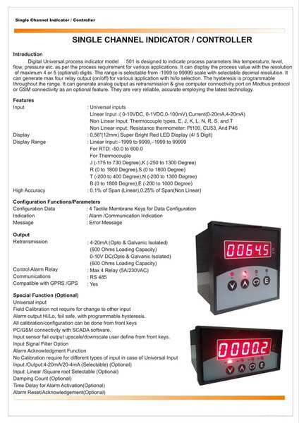
Process signal indicators are available in for 4-20mA/0-10VDC applications. Designed for easy programming (with only one-page manuals) and fast, no-hassle installation (with color-coded wire sensor terminals), they feature large, 4-digit LED displays that are easily read from a distance. These instruments are designed for use industry standard 4-20mA/0-10VDC signal applications, and offer a 24VDC power supply to power the signal loop. Inputs: Strain gauge, 4-20mA, 0-10VDC 24VDC signal excitation 2 alarm outputs Retransmission of process value: 4-20mA or 0-10VDC Engineering tech support available by email or phone Large inventory of same day shipping items Quick delivery on custom products NRG offer scalable input of pressure, two programmable alarms, and retransmission of process values. Models are available in 90-260VAC or with 24VDC power supply. Sensor excitation is supplied via a 10VDC supply for transducers and a 24VDC supply for amplified output transmitters. NRG 4-20mA loop-powered display provides a local display for 4-20mA transmitters with a 4-pin connection system. Additional Information: Production Capacity: 100 Delivery Time: EX STOCK Packaging Details: EXPORT WORTHY PACKING

Send Message
product image
Tank Level Indicator 3

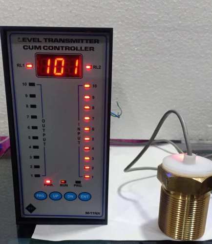
This is micro-processor based Donnelly Chute level Transmitter with isolated o/p (4-20 mA), 10nos digital optical o/p and 2 relay control .The instrument is field programmable and user friendly. In this Instrument user can set sensor sensitivity, sensor level selection, sample delay time and relay set point etc. The user can set level 2-10 then instrument automatically tunes for o/p 4-20 mA and display 0-100%. The instrument has five settable parameters like rL1,rL2,snt,trl,Lst. The Instrument reads input level in sequence 1 to 10 if misplaced any level then it will not show above levels. Operations Manual – Donnelly Chute Level Transmitter with Modbus Communication Model M11 NX Operations Manual – Donnelly Chute Level Transmitter with Modbus Communication Model M11 MAX Parameters Snt: Sensor Sensitivity adjustment Lst: Level Sensor selection (2-10) Trl: sample Delay adjustment RL1 and rL2 : Relay set point (0-100) snt(sensitivity adjustment Parameter) In this parameter user can set sensitivity of every (1-10 sensor) level sensor through key pad. The sensor value can be set in this parameter 93(Max.) to (185min.) sensitivity and it is normally set 100 value of every sensor. If snt set 93 then i/p led direct on without input connection. Lst(level selection parameter) The user can be set input level 2-10 then instrument automatically tune for o/p 4-20 mA and display 0-100% Trl = 20 set rL1,rL2 : Relay set point value Terminal Details S1 to S10 : i/p for probe type level sensor GND : Common terminal of probe sensor (Donnelly chute sensor) L1 to L10 :o/p for isolated digital out put to plc +24vdc : +v common (+24 vdc) for plc digital i/p O/p 4-20 mA : mA output (isolated) P : common terminal of Relay N/O : Normaly open terminal of Relay N/C : Normaly close terminal of relay L : Phase of 220v AC @50/60Hz N : Neutral E : Earth Specifications Main (auxiliary supply) : 220vAc +-15% @50 Hz O/P (Analog) : isolated 4-20mA O/p (digital : isolated digital output (L1 to L10) Relay set value : 000-100 settable Display range : 0-100% according select sensor level (2-10) settable Time delay setting : 001-100 ms settable Input :10nos. Probe sensor (digital i/p) Digital i/p / o/p : Indicate by LED as fitted on the front panel LED : Red Led for i/p, Green Led optical digital o/p Control Relay : one pair normally open potential free contact: @ 5A at 240v AC Overall size : 96x194x223 mm (WxHxD ) Panel cutout : 184X92mm(HxW) Configuration 1st press both PRG+ DN key for 5 seconds then display rL1 press ENT key display last load value if change then Use up/dn key and press ENT key display rL2 press ENT key display last load value if change then use up/dn key And press ENT key display snt press ENT display 001(it means level 1 select to adjust sensitivity) press ENT display last load value of sensor 1 sensitivity , if you want change value then use up/dn if value decrees (it means sensitivity higher side(93 max.) ) if value increase (it means sensitivity lower side(185 min.) if you want to store modified value then press and hold PRG key after press ENT key now release both key now modified value has been stored . If you do not want to change in this parameter then use only ENT key, if press only ENT key it means by pass snt parameter, if press PRG key and ENT key it means modified value stored and display snt for next level sensor sensitivity calibration And same process apply for level 1 to level 10 after that, Next parameter Lst display press ENT key display last level select if change (2-10) then use up/dn key press ENT key display trL press ENT key display last value and set 20 and press ENT key and now exit configuration mode.

Send Message

Still searching for
vendor catalog manual?