Vadodara
+919979119649

'lower side'

Items tagged with 'lower side'

product image
Magnetic Level Indicator

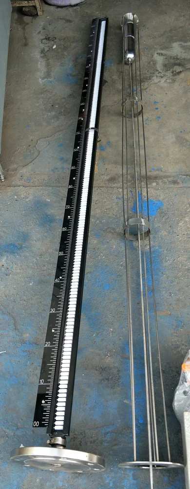
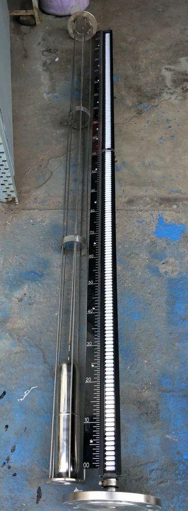
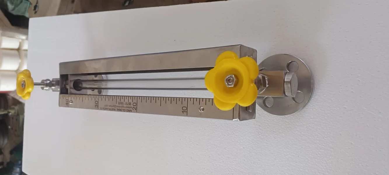
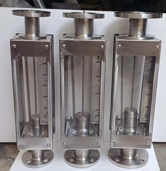
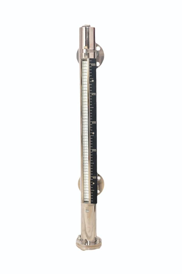
“NRG GLOBAL” make Magnetic Level Gauge provides clear, high clarity indication of liquid level. Magnetic Level Gauges are principally designed as an alternative to glass level gauges. NRG GLOBAL offers Magnetic Level Gauges in top-bottom, top and side mounted construction with two types of indicator system i.e. Capsule and Bi-colour Rollers. Magnetic Level Gauge is consists of three major components: Float Chamber, Float and Indicator System. Magnetic Level Gauge operates on the principle of magnetic field coupling to provide Fluid Level Information. Float chamber is typically constructed with nonmagnetic pipe having process Connections that matches to the vessel connections. Float size and weight is determined by the process fluid, pressure, temperature and the specific gravity of the process fluid. Float contains magnets to provide 360 ̊magnetic flux field.

Send Message
product image
Magnetic Level Indicator

“NRG GLOBAL” Top Mounted Magnetic Gauge is mounted on top of the tank by a suitable process connection preferably 100 mm NB flange. A float designed for the liquid to be gauged is guided within a stilling well that rest on the process flange. The float is connected to a stem that has a magnet at the upper end moving in a chamber. The float along with the stem and magnet moves up and down with the changing in liquid levels in the vessel. On the dry side of the chamber is the Magnetic Follower Display assembly comprising of a Red & Black PP magnetic capsule housed in a glass tube filled with water. As the float tracks the liquid level the magnet inside the float magnetically couples the Red & Black PP capsule and the capsule will remain magnetically coupled and the level can be read off directly TECHNICAL FEATURES •Simple and robust design. •Pressure and gas proof separation of chamber and display. •Measuring and indication of the level of aggressive, combustible, toxic, hot agitated and contaminated liquids. •Magnetic Follower display without external power. •Available for applications in all areas of industry through use of highly corrosion resistant materials •Designs for a pressure range from full vacuum to 30 bar •Designs for a temperature range from 100C to 250O C •Food industry design. •Interface measurement. OPTIONS: “NRG GLOBAL” Magnetic Switches are used to monitor certain limits of the level. The obtained binary signal can be forwarded to trigger alarms or other controls. • “NRG GLOBAL” Level Sensors are used to transmit the level in conjunction with a “NRG GLOBAL” control unit. This control unit converts the resistance value of the level sensor to a proportional analogue signal Additional Information: Production Capacity: 100 Delivery Time: WEEK Packaging Details: EXPORT WORTHY PAKING

Send Message
product image
Magnetic Level Indicator

“NRG GLOBAL INSTRUMENTS” Top Mounted Magnetic Gauge is mounted on top of the tank by a suitable process connection preferably 100 mm NB flange. A float designed for the liquid to be gauged is guided within a stilling well that rest on the process flange. The float is connected to a stem that has a magnet at the upper end moving in a chamber. The float along with the stem and magnet moves up and down with the changing in liquid levels in the vessel. On the dry side of the chamber is the Magnetic Follower Display assembly comprising of a Red & Black PP magnetic capsule housed in a glass tube filled with water. As the float tracks the liquid level the magnet inside the float magnetically couples the Red & Black PP capsule and the capsule will remain magnetically coupled and the level can be read off directly TECHNICAL FEATURES •Simple and robust design. •Pressure and gas proof separation of chamber and display. •Measuring and indication of the level of aggressive, combustible, toxic, hot agitated and contaminated liquids. •Magnetic Follower display without external power. •Available for applications in all areas of industry through use of highly corrosion resistant materials •Designs for a pressure range from full vacuum to 30 bar •Designs for a temperature range from 100C to 250O C •Food industry design. •Interface measurement. Additional Information: Item Code: TMMLI Production Capacity: 100 Delivery Time: EX STOCK Packaging Details: EXPORT WORTHY PACKING

Send Message
product image
Level Measurement

MAKE : NRG GLOBAL MODEL : TUBULAR SIDE MOUNTED TYPE : WITH VALVE FLUID : LIQUID TEMPERATURE : 150O C PRESSURE : VACCUME TO 6 Kg/Cm2 SPECIFIC GRAVITY / DENSITY : 0.7-1.2 VISCOSITY (OP / MAX) : 1 Cp WETTED PARTS (MOC) : SS 304 CONNECTION FLANGE : SS 304 SLIP ON TYPE CASING / GLASS PROTECTION : SS304 “C” TYPE CHANNEL HAVING 1 MM THICK GLASS TUBE : GLASS TUBE OF 19 MM OD SCALE : SS304 ENGRAVED OF 25 MM WIDTH WITH LC 5MM PACKING : 100 % PTFE GLAND : SS304 VALVE TYPE : SS304 INBUILT ISOLATION NEEDLE VALVE VALVE BODY : SS304 VENT PLUG : ½” BSP STOP PLUG DRAIN PLUG : ½” BSP STOP PLUG ACCESSOIRES : N. A. HYD TEST : 7 Kg/cm2 to Vacuum FASTENERS : SS304 CONNECTION SIZE : 1” ASA 150 # RF

Send Message
product image
Pressure Transmitter

Diaphragm seal systems are used for demanding measuring requirements with extreme medium temperatures of -90 °C up to +400 °C in the process industry. The diaphragm seal assemblies protect the measuring instrument from aggressive, corrosive, heterogeneous, abrasive, highly viscous or toxic media. With this service, the total costs of the diaphragm seal system can be clearly lowered. In this way, the service life of the measuring instrument can be fully utilised and only the diaphragm seal assembly needs replacement or repair, preventatively or after failure. With preventive maintenance, scheduled in line with planned shutdowns to your plant, you can reduce downtimes. Service can be done both on a mounted process transmitter as well as on a mechanical measuring instrument. Depending on the application case, the service life of the process transmitter is longer than that of the wetted parts. Therefore, only in rare cases must defective diaphragm seal systems be replaced completely, i.e. including the process transmitter. By re-using the process transmitter, WIKA offers a service package with clear cost savings. With the replacement service, through the exchange of the diaphragm seal, the TCO (total cost of ownership) of the measuring location can be reduced considerably. Your benefits Cost saving Fast availability by saving time Functional test of a process transmitter Current material test certificate New calibration of the entire system Additional Information: Production Capacity: 100 Delivery Time: WEEK Packaging Details: EXPORT WORTHY PACKING

Send Message
product image
Rotameter

“NRG” Make Metal Variable Area Type Flow Meter are designed to measure flow rate of liquids and gases under critical conditions. It consists of a tapered metal tube, an indicating assembly and float. A magnet encapsulated in float couples with rotating magnets are connected to an indicating pointer. Henceforth, the movement of the float is accurately indicated in terms of flowrate. They are intended for application where high pressure, temperature or corrosive conditions preclude the use of conventional glass tube. These are all Metal Variable Area Type Flow meter design to measure flow rate of Liquids & Gases under critical conditions. It consists of a tapered metal tube, an indicating assembly and a float. A magnet encapsulates in float couples with rotating magnets connected to an indicating pointer, thus the movement of the float, is accurately indicated in terms of flow rate. 2. Working Principle When fluid or gas flows through a taper tube containing a float, a pressure difference of P1 and P2 is created between upper and lower side of the float. The float moves upwards by a force obtained by multiplying the pressure differential by the maximum cross-sectional area of the float. Additional Information: Item Code: MTRM009 Production Capacity: 100 Delivery Time: WEEK Packaging Details: EXPORT WORTHY PACKING

Send Message
product image
Acrylic Rotameter

NRG GLOBAL INSTRUMENTS MAKE Glass Tube Variable Area Flow Meters (Rotameters) are intended for general in line and ByPass metering applications (i.e. for Gas & Liquid) where operating conditions are with the limitations of Glass metering tubes. These are the principle of Variable Area. The float moves freely up and down tapered borosilicate glass with fluid flow from bottom to top. The float takes up a position where buoyancy forces and the float weight are balanced in proportion to flow rate. The Vertical position of the float as indicated by scale is the measure of the instantaneous flow rate. 2. Principal of Operation When fluid or gas flows through a taper tube containing a float, a pressure difference of P1 and P2 is created between upper and lower side of the float. The float moves upwards by a force obtained by multiplying the pressure differential by the maximum cross-sectional area of the float. Due to taper tube, as the float moves upwards, the fluid passing area increases as a result of which the differential pressure decreases. Upward movement of float stops when the dead load is dynamically balanced by the differential pressure.

Send Message
product image
Flow Instruments

NRG GLOBAL MAKE Metal Variable Area Type Flow Meter are designed to measure flow rate of liquids and gases under critical conditions. It consists of a tapered metal tube, an indicating assembly and float. A magnet encapsulated in float couples with rotating magnets are connected to an indicating pointer. Henceforth, the movement of the float is accurately indicated in terms of flowrate. They are intended for application where high pressure, temperature or corrosive conditions preclude the use of conventional glass tube. These are all Metal Variable Area Type Flow meter design to measure flow rate of Liquids & Gases under critical conditions. It consists of a tapered metal tube, an indicating assembly and a float. A magnet encapsulates in float couples with rotating magnets connected to an indicating pointer, thus the movement of the float, is accurately indicated in terms of flow rate. 2. Working Principle When fluid or gas flows through a taper tube containing a float, a pressure difference of P1 and P2 is created between upper and lower side of the float. The float moves upwards by a force obtained by multiplying the pressure differential by the maximum cross-sectional area of the float. Based on Bemoulli's theorem, the principle mentioned above can be theoretically expressed as follows. Due to taper tube, as the float moves upwards, the fluid passing area increases as a result of which the differential pressure decreases. Upward movement of float stops when the dead load is dynamically balanced by the differential pressure. Tapering of metering tube is so designed that the vertical movement of the float becomes linearly proportional to the rate of flow and the scale is provided to read the position of the float, thusgiving birth to flow rate indication.

Send Message
product image
Tank Level Indicator 3

This is micro-processor based Donnelly Chute level Transmitter with isolated o/p (4-20 mA), 10nos digital optical o/p and 2 relay control .The instrument is field programmable and user friendly. In this Instrument user can set sensor sensitivity, sensor level selection, sample delay time and relay set point etc. The user can set level 2-10 then instrument automatically tunes for o/p 4-20 mA and display 0-100%. The instrument has five settable parameters like rL1,rL2,snt,trl,Lst. The Instrument reads input level in sequence 1 to 10 if misplaced any level then it will not show above levels. Operations Manual – Donnelly Chute Level Transmitter with Modbus Communication Model M11 NX Operations Manual – Donnelly Chute Level Transmitter with Modbus Communication Model M11 MAX Parameters Snt: Sensor Sensitivity adjustment Lst: Level Sensor selection (2-10) Trl: sample Delay adjustment RL1 and rL2 : Relay set point (0-100) snt(sensitivity adjustment Parameter) In this parameter user can set sensitivity of every (1-10 sensor) level sensor through key pad. The sensor value can be set in this parameter 93(Max.) to (185min.) sensitivity and it is normally set 100 value of every sensor. If snt set 93 then i/p led direct on without input connection. Lst(level selection parameter) The user can be set input level 2-10 then instrument automatically tune for o/p 4-20 mA and display 0-100% Trl = 20 set rL1,rL2 : Relay set point value Terminal Details S1 to S10 : i/p for probe type level sensor GND : Common terminal of probe sensor (Donnelly chute sensor) L1 to L10 :o/p for isolated digital out put to plc +24vdc : +v common (+24 vdc) for plc digital i/p O/p 4-20 mA : mA output (isolated) P : common terminal of Relay N/O : Normaly open terminal of Relay N/C : Normaly close terminal of relay L : Phase of 220v AC @50/60Hz N : Neutral E : Earth Specifications Main (auxiliary supply) : 220vAc +-15% @50 Hz O/P (Analog) : isolated 4-20mA O/p (digital : isolated digital output (L1 to L10) Relay set value : 000-100 settable Display range : 0-100% according select sensor level (2-10) settable Time delay setting : 001-100 ms settable Input :10nos. Probe sensor (digital i/p) Digital i/p / o/p : Indicate by LED as fitted on the front panel LED : Red Led for i/p, Green Led optical digital o/p Control Relay : one pair normally open potential free contact: @ 5A at 240v AC Overall size : 96x194x223 mm (WxHxD ) Panel cutout : 184X92mm(HxW) Configuration 1st press both PRG+ DN key for 5 seconds then display rL1 press ENT key display last load value if change then Use up/dn key and press ENT key display rL2 press ENT key display last load value if change then use up/dn key And press ENT key display snt press ENT display 001(it means level 1 select to adjust sensitivity) press ENT display last load value of sensor 1 sensitivity , if you want change value then use up/dn if value decrees (it means sensitivity higher side(93 max.) ) if value increase (it means sensitivity lower side(185 min.) if you want to store modified value then press and hold PRG key after press ENT key now release both key now modified value has been stored . If you do not want to change in this parameter then use only ENT key, if press only ENT key it means by pass snt parameter, if press PRG key and ENT key it means modified value stored and display snt for next level sensor sensitivity calibration And same process apply for level 1 to level 10 after that, Next parameter Lst display press ENT key display last level select if change (2-10) then use up/dn key press ENT key display trL press ENT key display last value and set 20 and press ENT key and now exit configuration mode.

Send Message

Still searching for
lower side?