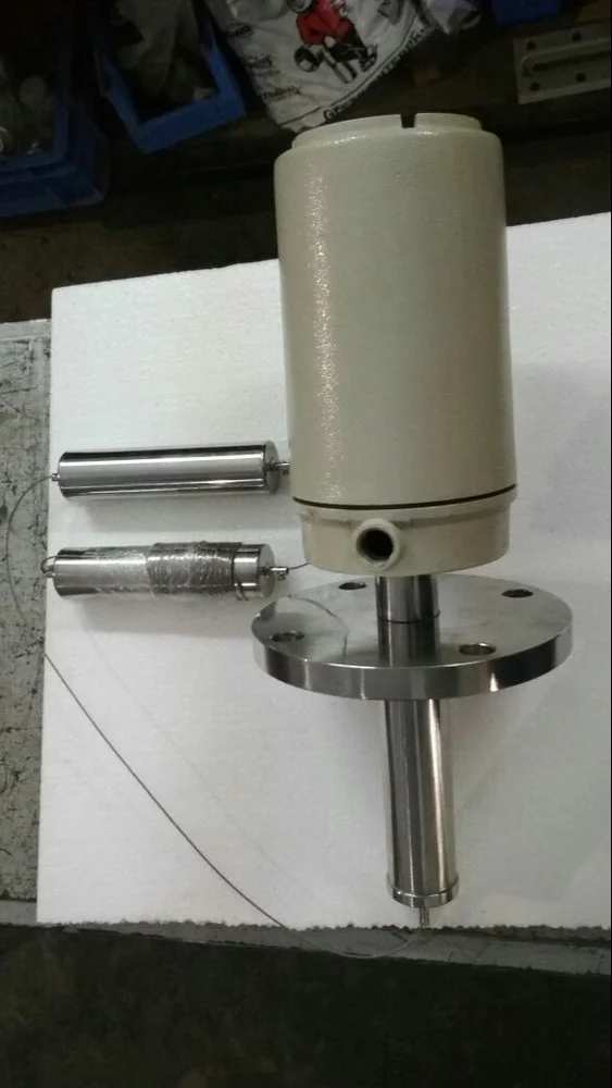
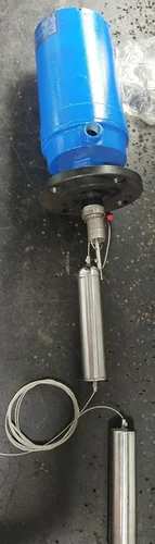
Vadodara
+919979119649

'intelligent operation'

Items tagged with 'intelligent operation'

product image
Flow Meter

· Full Bore Electromagnetic Flow Meter · Best Accuracy :- +/- 0.5 % Of Reading · Excellent Measuring Accuracy To Low Velocity, Measure Double Directions Flows · Buried Sensor (IP 68) No need Measure Well While Instillation; · Precision Coil Winding Technology, Make Magnetic Field More Uniform · Build-in Reference Electrode, No Need Connect Ground Ring; · Dual Frequency Excitation And Stubble Zero Point; · Self-Diagnostic Function, And Intelligent Operation APPLICATION: · ETP/STP Plant · Bore Well Water · Water Base Chemical Mixing Plant · Water Bathing Plant · Ro Plant · Starch Slurry · Food Mixing Plant · Pumping Station Additional Information: Production Capacity: 100 Delivery Time: WEEK Packaging Details: EXPORT WORTHY PACKING

Send Message
product image
FLOWMETER

NRG GLOBAL MAKE  Full Bore Electromagnetic Flow Meter  Best Accuracy :- +/- 0.5 % Of Reading  Excellent Measuring Accuracy To Low Velocity, Measure Double Directions Flows  Buried Sensor (IP 68) No need Measure Well While Instillation;  Precision Coil Winding Technology, Make Magnetic Field More Uniform  Build-in Reference Electrode, No Need Connect Ground Ring;  Dual Frequency Excitation And Stubble Zero Point;  Self-Diagnostic Function, And Intelligent Operation APPLICATION:  ETP/STP Plant  Bore Well Water  Water Base Chemical Mixing Plant  Water Bathing Plant  Ro Plant  Starch Slurry  Food Mixing Plant. Pumping Station

Send Message
product image
Level Switch

Conductivity Level Switch is a simple, low cost, point level measurement switch designed for level detection of conductive liquids having low densities, high viscosities, containing solid particles and to detect interface between non-conductive and conductive liquids. The probes work through the variation of the electrical resistance between the reference electrode and the level-control electrode. Conductivity level switches detect the level resistance when their electrodes are covered by the medium. If the tank is made of plastic, concrete, or any other nonconductive material, an additional electrode is required as a reference Conductivity Level Switches are available with stainless steel 316 electrodes as standard Suitable for many chemicals and aggressive media which are conductive in nature and dirty liquids, liquids with high solid content Construction available with both Solid probes & Suspended probes to suit fitting requirement It is a simple, low cost, point level controller designed for detecton of conductive liquids, having low densites, high viscosities, containing solid particles and interface between nonconductive and conductive liquids. CONSTRUCTION & OPERATION It comprises of a probe, wired to a level controller. The probe holds one common reference/common electrode and one or multiple “Control Electrodes” depending upon the number of levels to be controlled. All the electrodes are suitably insulated to avoid electrical bridging. The lengths of “Control Electrodes” correspond to the height of preset level points to be controlled and the length of the “reference/common Electrode” is kept slightly longer than the longest “Control Electrode”. If tank is conductive, it can be used as a reference/common electrode. Then number of control electrodes equals number of preset levels. Level controller houses sensing electronics consisting of power supply and signal conditoning circuit which provide a “Low AC Voltage” across mass and control electrodes. On liquid reaching preset level point electrical circuit gets completed - generating a signal which is amplified to actuate a relay, those potential free contacts are available for subsequent operations. On “Level Falling” the circuit breaks, deactivating the relay Additional Information: Production Capacity: 100 Delivery Time: WEEK Packaging Details: EXPORT WORTHY PAKING

Send Message
product image
Level Switch

NRG GLOBAL MAKE Displacer type level switches offers the industrial user a wide choice of alarm and control configuration. DLS works on a simple buoyancy principle and is well suited for simple or complex applications, such as forming surging liquids or agitated fluids, and usually costs less than other types of level switches. CONSTRUCTION & OPERATION Operation is based on simple buoyancy principle. As the liquid level rises and progressively immerses the displacer elements, the effective weight suspended on the spring reduces and the consequent length of the spring change is used to provide magnet movement and operate the switch. The spring movement causes the magnetic sleeve to attract a pivoted magnet actuating a switch mechanism located outside the barrier tube. Built-in limit stops, prevent over stroking under level surge conditions. FEATURES: • Wide choice of switching functions • Suitable for large tanks up to 15 meters • Site adjustable switch points • Customized for high temp, high pressure & vaccum applications. • Reliable performance in turbulent liquids even without still pipes. • Easy transportation of longer length switches. • Enclosure : Weather proof-IP-65 Ex-proof-Gr. IIA & IIB or IIC GENERAL SPECIFICATIONS: Enclosure : Cast ALUMINIUM, Weather Proof-IP 65, Cast AL Ex-proof Gr. IIA & IIB or IIC Conduit Connection : ¾ ” ET or ½” NPT Measuring Range : 200 mm~15000 mm Operating Differential : 40±5 mm / Adjustable / 65 ±5 mm Switch Type : Micro switch Switch Contacts : 2 SPDT (2 NO + 2 NC) @ 5A, 230 VAC (Resistive) Switch Action : Bistable Terminals : To suit 1.5 mm2 conductor Flexible Rope : SS304, SS316, PP, PTFE Displacer : SS304, SS316, PP, PTFE Spring Housing : SS316, PP, PTFE Spring Material : SS316, SS316L Process Connection Flanged : MS, SS304, SS316, PP (SS clad), PTFE (SS clad) Perforated still well : MS, SS304, SS316, PP (65 NB) External Cage : MS, SS304, SS316, PP (80 NB) Max. Temperature : 0-200°C (without cooling fins) 0-300°C (with cooling fins) (Contact factory for temperature more than 300°C) Max. Test Pressure : Vaccum to 40 Kg/cm2 (Contact factory for pressure more than 40 Kg/cm2) Min. Sp. Gravity : 0.7 (Contact factory for Sp. Gr. less than 0.7)

Send Message
product image
Acrylic Rotameter

NRG GLOBAL INSTRUMENTS MAKE Glass Tube Variable Area Flow Meters (Rotameters) are intended for general in line and ByPass metering applications (i.e. for Gas & Liquid) where operating conditions are with the limitations of Glass metering tubes. These are the principle of Variable Area. The float moves freely up and down tapered borosilicate glass with fluid flow from bottom to top. The float takes up a position where buoyancy forces and the float weight are balanced in proportion to flow rate. The Vertical position of the float as indicated by scale is the measure of the instantaneous flow rate. 2. Principal of Operation When fluid or gas flows through a taper tube containing a float, a pressure difference of P1 and P2 is created between upper and lower side of the float. The float moves upwards by a force obtained by multiplying the pressure differential by the maximum cross-sectional area of the float. Due to taper tube, as the float moves upwards, the fluid passing area increases as a result of which the differential pressure decreases. Upward movement of float stops when the dead load is dynamically balanced by the differential pressure.

Send Message
product image
Displacer Level Switch

NRG GLOBAL MAKE Displacer type level switches offers the industrial user a wide choice of alarm and control configuration. DLS works on a simple buoyancy principle and is well suited for simple or complex applications, such as forming surging liquids or agitated fluids, and usually costs less than other types of level switches. CONSTRUCTION & OPERATION Operation is based on simple buoyancy principle. As the liquid level rises and progressively immerses the displacer elements, the effective weight suspended on the spring reduces and the consequent length of the spring change is used to provide magnet movement and operate the switch. The spring movement causes the magnetic sleeve to attract a pivoted magnet actuating a switch mechanism located outside the barrier tube. Built-in limit stops, prevent over stroking under level surge conditions. FEATURES: • Wide choice of switching functions • Suitable for large tanks up to 15 meters • Site adjustable switch points • Customized for high temp, high pressure & vaccum applications. • Reliable performance in turbulent liquids even without still pipes. • Easy transportation of longer length switches. • Enclosure : Weather proof-IP-65 Ex-proof-Gr. IIA & IIB or IIC

Send Message
product image
Tank Level Indicator 3

This is micro-processor based Donnelly Chute level Transmitter with isolated o/p (4-20 mA), 10nos digital optical o/p and 2 relay control .The instrument is field programmable and user friendly. In this Instrument user can set sensor sensitivity, sensor level selection, sample delay time and relay set point etc. The user can set level 2-10 then instrument automatically tunes for o/p 4-20 mA and display 0-100%. The instrument has five settable parameters like rL1,rL2,snt,trl,Lst. The Instrument reads input level in sequence 1 to 10 if misplaced any level then it will not show above levels. Operations Manual – Donnelly Chute Level Transmitter with Modbus Communication Model M11 NX Operations Manual – Donnelly Chute Level Transmitter with Modbus Communication Model M11 MAX Parameters Snt: Sensor Sensitivity adjustment Lst: Level Sensor selection (2-10) Trl: sample Delay adjustment RL1 and rL2 : Relay set point (0-100) snt(sensitivity adjustment Parameter) In this parameter user can set sensitivity of every (1-10 sensor) level sensor through key pad. The sensor value can be set in this parameter 93(Max.) to (185min.) sensitivity and it is normally set 100 value of every sensor. If snt set 93 then i/p led direct on without input connection. Lst(level selection parameter) The user can be set input level 2-10 then instrument automatically tune for o/p 4-20 mA and display 0-100% Trl = 20 set rL1,rL2 : Relay set point value Terminal Details S1 to S10 : i/p for probe type level sensor GND : Common terminal of probe sensor (Donnelly chute sensor) L1 to L10 :o/p for isolated digital out put to plc +24vdc : +v common (+24 vdc) for plc digital i/p O/p 4-20 mA : mA output (isolated) P : common terminal of Relay N/O : Normaly open terminal of Relay N/C : Normaly close terminal of relay L : Phase of 220v AC @50/60Hz N : Neutral E : Earth Specifications Main (auxiliary supply) : 220vAc +-15% @50 Hz O/P (Analog) : isolated 4-20mA O/p (digital : isolated digital output (L1 to L10) Relay set value : 000-100 settable Display range : 0-100% according select sensor level (2-10) settable Time delay setting : 001-100 ms settable Input :10nos. Probe sensor (digital i/p) Digital i/p / o/p : Indicate by LED as fitted on the front panel LED : Red Led for i/p, Green Led optical digital o/p Control Relay : one pair normally open potential free contact: @ 5A at 240v AC Overall size : 96x194x223 mm (WxHxD ) Panel cutout : 184X92mm(HxW) Configuration 1st press both PRG+ DN key for 5 seconds then display rL1 press ENT key display last load value if change then Use up/dn key and press ENT key display rL2 press ENT key display last load value if change then use up/dn key And press ENT key display snt press ENT display 001(it means level 1 select to adjust sensitivity) press ENT display last load value of sensor 1 sensitivity , if you want change value then use up/dn if value decrees (it means sensitivity higher side(93 max.) ) if value increase (it means sensitivity lower side(185 min.) if you want to store modified value then press and hold PRG key after press ENT key now release both key now modified value has been stored . If you do not want to change in this parameter then use only ENT key, if press only ENT key it means by pass snt parameter, if press PRG key and ENT key it means modified value stored and display snt for next level sensor sensitivity calibration And same process apply for level 1 to level 10 after that, Next parameter Lst display press ENT key display last level select if change (2-10) then use up/dn key press ENT key display trL press ENT key display last value and set 20 and press ENT key and now exit configuration mode.

Send Message
product image
Flow Rotameter

1. PRODUCT DESCRIPTIONNRG GLOBAL INSTRUMENTS MAKE Glass Tube Variable Area Flow Meters (Rotameters) are intended for general in line and ByPass metering applications (i.e. for Gas & Liquid) where operating conditions are with the limitations of Glass metering tubes. These are the principle of Variable Area.The float moves freely up and down tapered borosilicate glass with fluid flow from bottom to top. The float takes up a position where buoyancy forces and the float weight are balanced in proportion to flow rate. The Vertical position of the float as indicated by scale is the measure of the instantaneous flow rate.2. PRINCIPAL OF OPERATIONWhen fluid or gas flows through a taper tube containing a float, a pressure difference of P1 and P2 is created between upper and lower side of the float. The float moves upwards by a force obtained by multiplying the pressure differential by the maximum cross-sectional area of the float. Due to taper tube, as the float moves upwards, the fluid passing area increases as a result of which the differential pressure decreases. Upward movement of float stops when the deadload is dynamically balanced by the differential pressure.

Send Message

Still searching for
intelligent operation?