Vadodara
+919979119649

'250 bar'

Items tagged with '250 bar'

product image
Magnetic Level Indicator

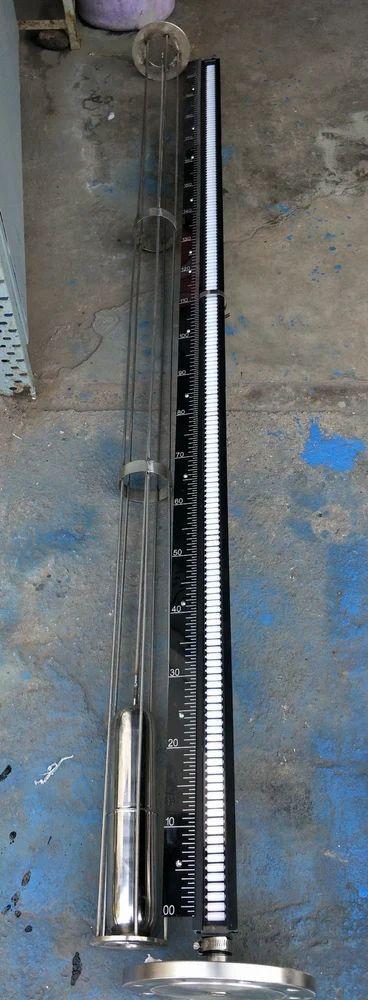
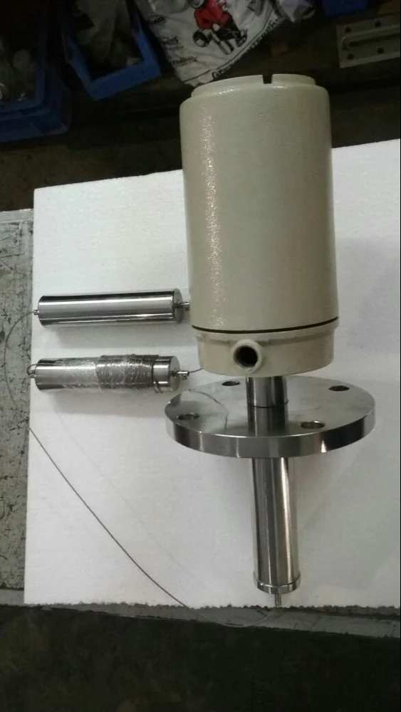
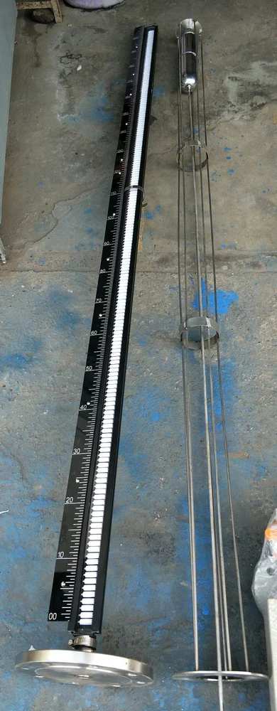
“NRG GLOBAL” Top Mounted Magnetic Gauge is mounted on top of the tank by a suitable process connection preferably 100 mm NB flange. A float designed for the liquid to be gauged is guided within a stilling well that rest on the process flange. The float is connected to a stem that has a magnet at the upper end moving in a chamber. The float along with the stem and magnet moves up and down with the changing in liquid levels in the vessel. On the dry side of the chamber is the Magnetic Follower Display assembly comprising of a Red & Black PP magnetic capsule housed in a glass tube filled with water. As the float tracks the liquid level the magnet inside the float magnetically couples the Red & Black PP capsule and the capsule will remain magnetically coupled and the level can be read off directly TECHNICAL FEATURES •Simple and robust design. •Pressure and gas proof separation of chamber and display. •Measuring and indication of the level of aggressive, combustible, toxic, hot agitated and contaminated liquids. •Magnetic Follower display without external power. •Available for applications in all areas of industry through use of highly corrosion resistant materials •Designs for a pressure range from full vacuum to 30 bar •Designs for a temperature range from 100C to 250O C •Food industry design. •Interface measurement. OPTIONS: “NRG GLOBAL” Magnetic Switches are used to monitor certain limits of the level. The obtained binary signal can be forwarded to trigger alarms or other controls. • “NRG GLOBAL” Level Sensors are used to transmit the level in conjunction with a “NRG GLOBAL” control unit. This control unit converts the resistance value of the level sensor to a proportional analogue signal Additional Information: Production Capacity: 100 Delivery Time: WEEK Packaging Details: EXPORT WORTHY PAKING

Send Message
product image
Magnetic Level Indicator

“NRG GLOBAL INSTRUMENTS” Top Mounted Magnetic Gauge is mounted on top of the tank by a suitable process connection preferably 100 mm NB flange. A float designed for the liquid to be gauged is guided within a stilling well that rest on the process flange. The float is connected to a stem that has a magnet at the upper end moving in a chamber. The float along with the stem and magnet moves up and down with the changing in liquid levels in the vessel. On the dry side of the chamber is the Magnetic Follower Display assembly comprising of a Red & Black PP magnetic capsule housed in a glass tube filled with water. As the float tracks the liquid level the magnet inside the float magnetically couples the Red & Black PP capsule and the capsule will remain magnetically coupled and the level can be read off directly TECHNICAL FEATURES •Simple and robust design. •Pressure and gas proof separation of chamber and display. •Measuring and indication of the level of aggressive, combustible, toxic, hot agitated and contaminated liquids. •Magnetic Follower display without external power. •Available for applications in all areas of industry through use of highly corrosion resistant materials •Designs for a pressure range from full vacuum to 30 bar •Designs for a temperature range from 100C to 250O C •Food industry design. •Interface measurement. Additional Information: Item Code: TMMLI Production Capacity: 100 Delivery Time: EX STOCK Packaging Details: EXPORT WORTHY PACKING

Send Message
product image
Flow Rotameter

Metal Variable Area Type Flow Meter are designed to measure flow rate of liquids and gases under critical conditions. It consists of a tapered metal tube, an indicating assembly and float. A magnet encapsulated in float couples with rotating magnets are connected to an indicating pointer. Henceforth, the movement of the float is accurately indicated in terms of flowrate. They are intended for application where high pressure, temperature or corrosive conditions preclude the use of conventional glass tube. These are all Metal Variable Area Type Flow meter design to measure flow rate of Liquids & Gases under critical conditions. It consists of a tapered metal tube, an indicating assembly and a float. A magnet encapsulates in float couples with rotating magnets connected to an indicating pointer, thus the movement of the float, is accurately indicated in terms of flow rate. 2. Working Principle When fluid or gas flows through a taper tube containing a float, a pressure difference of P1 and P2 is created between upper and lower side of the float. The float moves upwards by a force obtained by multiplying the pressure differential by the maximum cross-sectional area of the float. Based on Bemoulli's theorem, the principle mentioned above can be theoretically expressed as follows. Due to taper tube, as the float moves upwards, the fluid passing area increases as a result of which the differential pressure decreases. Upward movement of float stops when the dead load is dynamically balanced by the differential pressure. Tapering of metering tube is so designed that the vertical movement of the float becomes linearly proportional to the rate of flow and the scale is provided to read the position of the float, thus giving birth to flow rate indication. 3. Specifications Accuracy : ± 2% of FSD Rangeability : 10:1 Repeatability : ± 0.5% Temperature Rating : -200 to 250°C Pressure Rating : 40 Bar Flow Direction : Bottom to Top Connections : Flanged, TC End and Screwed Enclosure : IP 65 Weatherproof 4. Design features 1. Simplified piping and reduced space requirements 2. Permanent magnetic link between metering float and motion position transmitter 3. Precision swaged metering tube 4. Guide cartridges easily removable for cleaning 5. Provide with Electrical transmitter, flow indicator or alarm 6. Available F/F Height in 350, 450, 500 mm 7. Available Flange size 15 NB to 150 NB & Flow 200 LPH to 50,000 LPH

Send Message
product image
Industrial Rotameter

Metal Variable Area Type Flow Meter are designed to measure flow rate of liquids and gases under critical conditions. It consists of a tapered metal tube, an indicating assembly and float. A magnet encapsulated in float couples with rotating magnets are connected to an indicating pointer. Henceforth, the movement of the float is accurately indicated in terms of flowrate. They are intended for application where high pressure, temperature or corrosive conditions preclude the use of conventional glass tube. These are all Metal Variable Area Type Flow meter design to measure flow rate of Liquids & Gases under critical conditions. It consists of a tapered metal tube, an indicating assembly and a float. A magnet encapsulates in float couples with rotating magnets connected to an indicating pointer, thus the movement of the float, is accurately indicated in terms of flow rate. 2. Working Principle When fluid or gas flows through a taper tube containing a float, a pressure difference of P1 and P2 is created between upper and lower side of the float. The float moves upwards by a force obtained by multiplying the pressure differential by the maximum cross-sectional area of the float. Based on Bemoulli's theorem, the principle mentioned above can be theoretically expressed as follows. Due to taper tube, as the float moves upwards, the fluid passing area increases as a result of which the differential pressure decreases. Upward movement of float stops when the dead load is dynamically balanced by the differential pressure. Tapering of metering tube is so designed that the vertical movement of the float becomes linearly proportional to the rate of flow and the scale is provided to read the position of the float, thus giving birth to flow rate indication. 3. Specifications Accuracy : ± 2% of FSD Rangeability : 10:1 Repeatability : ± 0.5% Temperature Rating : -200 to 250°C Pressure Rating : 40 Bar Flow Direction : Bottom to Top Connections : Flanged, TC End and Screwed Enclosure : IP 65 Weatherproof 4. Design features 1. Simplified piping and reduced space requirements 2. Permanent magnetic link between metering float and motion position transmitter 3. Precision swaged metering tube 4. Guide cartridges easily removable for cleaning 5. Provide with Electrical transmitter, flow indicator or alarm 6. Available F/F Height in 350, 450, 500 mm 7. Available Flange size 15 NB to 150 NB & Flow 200 LPH to 50,000 LPH

Send Message
product image
Level Switch

NRG GLOBAL MAKE Displacer type level switches offers the industrial user a wide choice of alarm and control configuration. DLS works on a simple buoyancy principle and is well suited for simple or complex applications, such as forming surging liquids or agitated fluids, and usually costs less than other types of level switches. CONSTRUCTION & OPERATION Operation is based on simple buoyancy principle. As the liquid level rises and progressively immerses the displacer elements, the effective weight suspended on the spring reduces and the consequent length of the spring change is used to provide magnet movement and operate the switch. The spring movement causes the magnetic sleeve to attract a pivoted magnet actuating a switch mechanism located outside the barrier tube. Built-in limit stops, prevent over stroking under level surge conditions. FEATURES: • Wide choice of switching functions • Suitable for large tanks up to 15 meters • Site adjustable switch points • Customized for high temp, high pressure & vaccum applications. • Reliable performance in turbulent liquids even without still pipes. • Easy transportation of longer length switches. • Enclosure : Weather proof-IP-65 Ex-proof-Gr. IIA & IIB or IIC GENERAL SPECIFICATIONS: Enclosure : Cast ALUMINIUM, Weather Proof-IP 65, Cast AL Ex-proof Gr. IIA & IIB or IIC Conduit Connection : ¾ ” ET or ½” NPT Measuring Range : 200 mm~15000 mm Operating Differential : 40±5 mm / Adjustable / 65 ±5 mm Switch Type : Micro switch Switch Contacts : 2 SPDT (2 NO + 2 NC) @ 5A, 230 VAC (Resistive) Switch Action : Bistable Terminals : To suit 1.5 mm2 conductor Flexible Rope : SS304, SS316, PP, PTFE Displacer : SS304, SS316, PP, PTFE Spring Housing : SS316, PP, PTFE Spring Material : SS316, SS316L Process Connection Flanged : MS, SS304, SS316, PP (SS clad), PTFE (SS clad) Perforated still well : MS, SS304, SS316, PP (65 NB) External Cage : MS, SS304, SS316, PP (80 NB) Max. Temperature : 0-200°C (without cooling fins) 0-300°C (with cooling fins) (Contact factory for temperature more than 300°C) Max. Test Pressure : Vaccum to 40 Kg/cm2 (Contact factory for pressure more than 40 Kg/cm2) Min. Sp. Gravity : 0.7 (Contact factory for Sp. Gr. less than 0.7)

Send Message
product image
Flow Meter

NRG GLOBAL OFFER WATERMETERDOMESTIC WATER METER SPECIFICATIONS (15MM, 20MM AND 25MM SIZES) 1.1 GENERAL LAYOUT The complete water meter is to consist of (5) components:  Above ground extruded water meter box and extended lid with slider.  A water meter (Plastic bodied 15mm, 20mm and 25mm) class C volumetric rotary piston liquid sealed register) with unique meter serial number where first two digits indicate year of manufacture.  3 way concentric restrictor valve.  SABS (Blue) lever type consumer ball valve.  Fusion welded PPR pipe assembly tested to 25 bar Additional Information: Production Capacity: 100 Delivery Time: WEEK Packaging Details: CORUGATED BOX

Send Message
product image
Glass Tube Rotameter

MAKE : NRG GLOBAL HSN CODE : 90261020 TYPE : GLASS TUBE ROTAMETER Name of the Fluid : LDO Temperature : 40 - 55 Deg C Pressure : 8 BAR Specific Gravity / Density : 0.267 Viscosity : PL SPECIFY M. RANGE : 0-150 Lit/Hr MOC (WETTEC PARTS) : SS 304 End Connection : SS 304 FLANGED END Process Connection : 1/2” ASA 150 # RF Float Material : SS 304 Float Retainer : PP Tube Material : GERMAN TAPER BOROSILICATE GLASS TUBE Packing/O-Ring Material : PTFE GLAND : CS BODY / COVER : MS POWDER COATED Scale : ACRYLIC ENGRAVED Scale Length : 50 – 150 mm Approx. Rangebility : 10:1 Scale Marking : In LPH Accuracy : ±2% F.S.D. Inlet Conn. Orientation : BOTTOM Outlet Conn. Orientation : TOP FASTNERS : S.S.304 F/F HIEGHT : 500 MM

Send Message

Still searching for
250 bar?